CCNA | P3: Implementing VLANs and STP | C2: Spanning Tree Protocol Concepts
Unraveling the Mysteries of Spanning Tree Protocol
Lesson Contents
- What is Spanning Tree Protocol?
- What are BPDUs(Bridge Protocol Data Units)
- Shortcomings of STP
- STP Port States: A Closer Look
- The Intricacies of Switch Port Operations and Spanning Tree Protocol
- The Root Bridge Election: A Game of Thrones
- Best Practices for STP: Winning Strategies
- Illustrations of example Topologies STP
- Identifying Root Bridge
- Network Convergence
- Rapid Spanning Tree Protocol (RSTP)
- Port Roles in RSTP
- Port States in RSTP
- RSTP Port/Link Types
- EtherChannel
- BDPU Guard
- PortFast
- RootGuard
- LoopGuard
- Conclusion
What is Spannig Tree Protocol ?
Imagine you’re navigating a network of switches, and you’re curious about how they manage broadcast traffic.
Broadcast traffic is like a town crier in a medieval village, sending a message to all other devices on the same network segment.
While this can be beneficial for certain tasks, it can also lead to complications if there’s a loop in the network topology.
Think of a loop as a roundabout with multiple exits leading to the same destination, creating a cycle.
This can occur if you connect two switches with more than one cable, or if you have backup links for redundancy.
Loops are the villains of network topology because they can trigger broadcast storms.
These storms occur when broadcast traffic keeps circulating around the loop, gobbling up all the network resources.
This can result in the network moving at a snail’s pace or even crashing.
To combat this, our network heroes, the switches, employ a protocol known as the Spanning Tree Protocol (STP). STP, defined in the IEEE 802.1D standard (a part of the 802.1Q standard for VLANs), operates by exchanging special messages called Bridge Protocol Data Units (BPDUs) between switches.
What are BPDUs(Bridge Protocol Data Units)
BPDUs are like little packets of information containing details about the switch ID, the port ID, and the path cost to the root bridge.
The root bridge is the switch with the lowest ID in the network and serves as the reference point for STP.
Through the exchange of BPDUs, switches can map out the network topology and detect loops.
They then make executive decisions on which ports to block or unblock to break the loops and create a loop-free spanning tree.
The spanning tree is like a well-planned highway system that connects all the switches without any loops. This way, only one path is used for broadcast traffic, while the other paths are kept as backup routes in case of a roadblock or failure.
When a link fails or a new switch is added to the network, STP acts like a traffic controller, detecting the change and recalculating the spanning tree. This process, known as convergence, can take some time depending on the size and configuration of the network. During convergence, some ports may be temporarily blocked or unblocked, which can cause brief interruptions in network connectivity.
While STP is a crucial protocol for layer 2 networks, it’s not without its limitations and drawbacks.
Shortcomings of STP
For instance, STP blocks some links that could be utilized for load balancing or increasing bandwidth.
It also uses a fixed algorithm to select the root bridge and the port roles, which may not be the best fit for some scenarios.
Moreover, STP’s convergence time is slower compared to some of its newer counterparts.
To overcome these challenges, several enhancements and variations of STP have been developed over time, such as the Rapid Spanning Tree Protocol (RSTP), Multiple Spanning Tree Protocol (MSTP), and Per-VLAN Spanning Tree Protocol (PVST+).
These protocols offer faster convergence, more flexibility, and better performance than STP. However, they still adhere to the same principles and use BPDUs for communication.
STP Port States: A Closer Look
A port on a switch can be in one of the following states:
-
Forwarding: The port is actively sending and receiving frames, and participating in the STP process. This is the normal state for a port that is part of the best path to the Root Bridge.
-
Blocking (Discarding in Rapid STP or RSTP): The port is not sending or receiving any frames, except for BPDUs, which are special frames that carry STP information. This state is used to prevent loops on redundant links.
-
Listening (not in RSTP): The port is not sending or receiving any frames, but it is listening to incoming frames to remove any outdated MAC address entries from its table. This state is used to avoid temporary loops when a port transitions from blocking to forwarding.
-
Learning: The port is not sending or receiving any frames, but it is listening to incoming frames to learn MAC addresses and populate its table. This state is used to prepare the port for forwarding.
-
Disabled: The port is administratively shut down or has a physical problem. It does not participate in the STP process. This is like a closed road or a road under construction in our highway analogy.
The Intricacies of Switch Port Operations and Spanning Tree Protocol
Imagine a switch port coming online, like a new player entering a game.
It starts in the blocking state, akin to a player on the bench, ready to send a Hello BPDU.
This Hello BPDU is like a friendly wave, a message that a switch sends to communicate with other switches in the network. It carries the following crucial information:
-
Root bridge ID: This is the identifier of the switch that the sender believes is the root bridge, the kingpin of the network.
-
Sender bridge ID: This is the identifier of the switch sending the message, akin to a player’s jersey number.
-
Sender root cost: This is the cost of the path from the sender to the root bridge, calculated based on the speed and bandwidth of the links, like the effort it takes to pass the ball from one player to another.
-
Timer values: These are the values set by the root bridge and adopted and forwarded by other switches. They control how often and how long the switches send and wait for Hello BPDUs. They include:
- Hello: This is the interval between each Hello BPDU, typically 2 seconds.
- MaxAge: This is the maximum time that a switch will wait without receiving Hello BPDUs before it assumes that there is a change in the network topology, usually 20 seconds (10 times the Hello interval).
- Forwarding delay: This is the time that a switch will spend in each of the transient states when there is a change in the network topology. The transient states are listening and learning, and they occur in that order. The switch will listen for new information and learn new addresses before forwarding data. The forwarding delay is usually 15 seconds for each state.
If there is no loop on the link, it will eventually transition to the forwarding state after all the switches have elected a root bridge and identified their loop-free link to it.
The time it takes for a port to transition depends on the STP timers and the type of STP, much like how a player’s time on the field depends on the game’s rules and strategies.
The Root Bridge Election: A Game of Thrones
The Root Bridge is the MVP in the STP topology, as it determines the best paths for all other switches. The Root Bridge is elected based on its Bridge ID (BID), a unique identifier composed of two parts:
-
Bridge Priority: A configurable value that ranges from 0 to 65535, with 32768 being the default. The lower the priority, the higher the chance of becoming the Root Bridge.
-
System ID: A value derived from the switch’s MAC address. The lower the MAC address, the higher the chance of becoming the Root Bridge.
When switches start up, they send BPDUs with their own BIDs as root. When they receive a BPDU with a better BID (lower priority or lower MAC address), they update their root BID and forward it to their neighbors. Eventually, all switches will agree on the same root BID, and the switch with that BID will become the Root Bridge, much like a team electing their captain.
Best Practices for STP: Winning Strategies
While STP is enabled by default on switches and they will automatically run the STP process without any configuration, this may not result in optimal network performance or stability. Therefore, it’s recommended to follow some best practices for STP, akin to following winning strategies in a game:
-
Manually select a Root Bridge that has high bandwidth and low latency, and is located centrally in the network. This can be done by lowering its bridge priority or using commands such as root primary or root secondary.
-
Manually select backup Root Bridges that can take over if the primary one fails. This can be done by setting their bridge priority slightly higher than the primary one.
-
Use RSTP or other variants of STP that have faster convergence and more features than the original STP.
-
Use PortFast on ports that connect to end devices such as PCs or servers, to skip the listening and learning states and go directly to forwarding. This can reduce delays and improve user experience.
-
Use BPDU Guard on PortFast ports to prevent rogue switches from connecting and causing loops or topology changes. This can enhance security and stability.
Illustrations of example Topologies STP
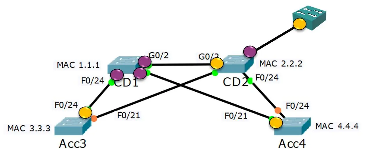
DIAGRAM 1:
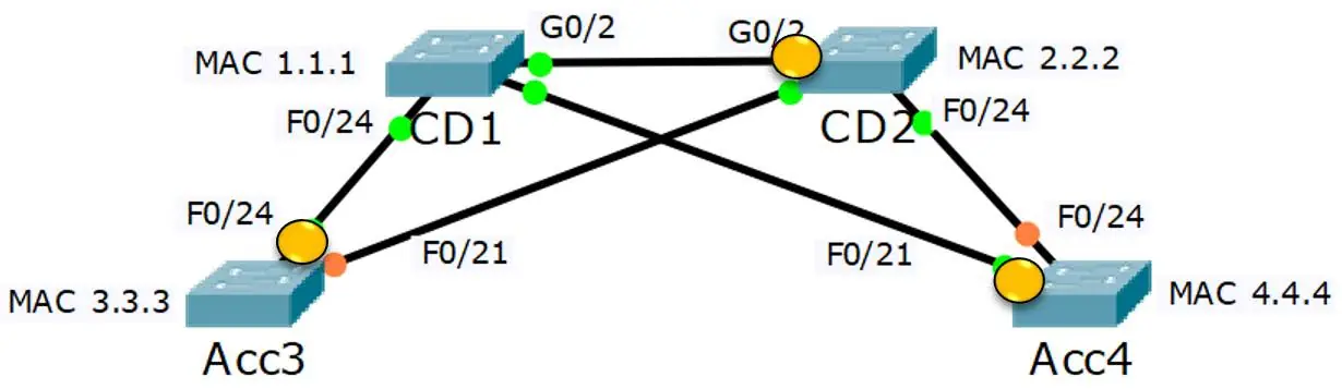
In this network, we have four switches: CD1, CD2, Acc3, and Acc4. None of these switches have been configured with a Bridge Priority, so the switch with the lowest MAC address, CD1, naturally becomes the Root Bridge. It’s like CD1 winning the title of ‘captain’ due to its seniority!
The other switches, CD2, Acc3, and Acc4, calculate their distance to the Root Bridge based on the bandwidth of the links and the Port Priority (if set).
It’s like these switches are determining their positions on the field relative to the captain.
The links with the lowest cost to reach the Root Bridge are put into a forwarding state.
These are the most efficient routes to the Root Bridge, much like the quickest paths to the captain on the field.
The interface on each switch that connects to the lowest cost link is designated as the Root Port. These are the ‘star players’ that have the best connection to the captain.
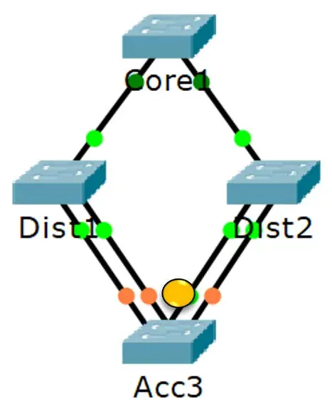
Diagram 2:
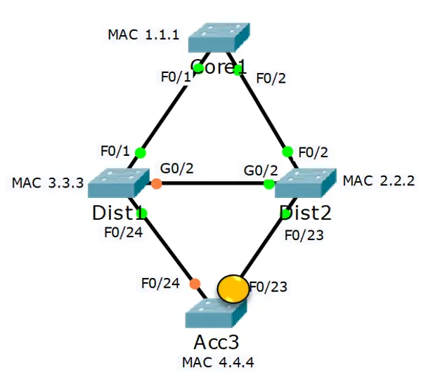
In this depicted network, we have four switches: Core1, Dist1, Dist2, and Acc3. The path selection is based on the lowest cost, which is calculated from the link speed and the port priority. It’s like choosing the quickest route in a race, considering both distance and terrain.
For instance, Acc3 has two equal cost paths to reach the Root Bridge Core1, one through Dist1 and one through Dist2. However, it will only use the path through Dist2, because Dist2 has a lower Bridge ID than Dist1. This decision helps Acc3 avoid creating a loop in the network, much like a runner would choose the most efficient path in a race.
This example beautifully demonstrates how STP ensures efficient communication within a network of switches, highlighting the importance of the Root Bridge, the calculation of path costs, and the strategic selection of paths.
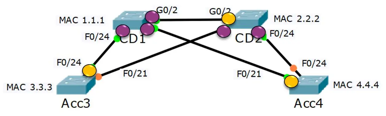
Diagram 3:
In this network scenario, Acc3 is faced with multiple paths to reach the Root Bridge, Core1. However, it doesn’t randomly select a path. Instead, it chooses the path via the left-hand link to Dist2. Why? Because this port has the lowest Port ID going to the switch with the lowest Bridge ID. It’s like choosing the shortest queue at a grocery store checkout!
Acc3 also shows strategic restraint by not selecting any of the other three links. This decision prevents the formation of a potential loop back to itself from the upstream switch. It’s like avoiding a path that could lead you back to where you started.
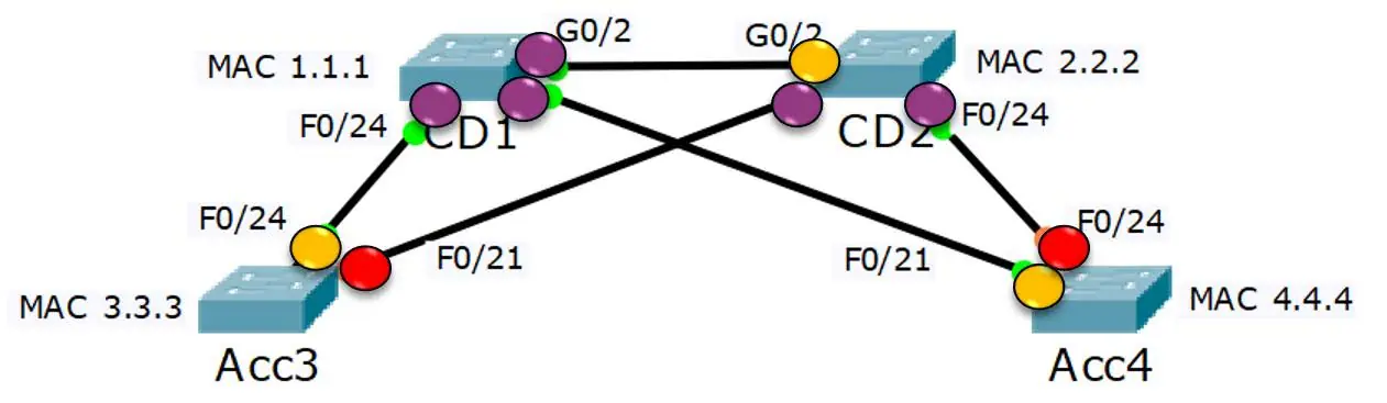
Diagram 4:
In the context of STP, the ports on the neighbor switch opposite the Root Port are indeed Designated Ports. These ports point away from the Root Bridge, serving as the exit points for data traffic.
On the other hand, Root Ports point towards the Root Bridge, acting as the entry points for data traffic. They represent the most direct paths to the Root Bridge.
All ports on the Root Bridge are always Designated Ports, as they distribute data traffic to the rest of the network.
Both Root Ports and Designated Ports transition to a forwarding state, ensuring efficient and loop-free data traffic in the network. This transition is akin to opening a gate, allowing data to flow freely to and from the Root Bridge.
Diagram 5:
On the remaining links, the switches are like contestants in a game, each trying to determine which of them has the least-cost path to the Root Bridge. If they find themselves in a tie, with equal cost paths, then the Bridge ID is used as a tiebreaker, much like a sudden death round in a game.
The port connecting the winning switch to the link is then selected as a Designated Port. These Designated Ports are like the champions of their respective switches, chosen for their direct paths to the Root Bridge.
This process ensures that there’s always a clear, loop-free path for data traffic to flow through the network, maintaining efficiency and stability.
Diagram 6:
In the grand scheme of STP, any ports that have not been selected as a Root Port or Designated Port pair could potentially form a loop. These ports are like the unsung heroes of the network, stepping back from the action to maintain the overall health and efficiency of the network.
These ports are selected as Blocking Ports. They’re like the guards of a castle, blocking any traffic that could potentially cause a loop in the network. While they might seem inactive, their role is crucial in maintaining a loop-free and efficient network topology.
Identifying Root Bridge
Identify the Root Bridge: This is the first step in STP. The Root Bridge is the switch with the best (lowest) Bridge ID.
-
Designated Ports on the Root Bridge: All ports on the Root Bridge are automatically Designated Ports. They are the exit points for data traffic from the Root Bridge.
-
Identify the Root Ports: On the other switches, determine the Root Ports. These are the ports with the lowest cost path to the Root Bridge. They act as the entry points for data traffic to the Root Bridge.
-
Designated Ports on the Neighbor Switches: The ports on the neighbor switches that connect to the Root Ports are Designated Ports. They point away from the Root Bridge and are the exit points for data traffic.
-
Blocking Ports: On the remaining links, one port will be Blocking to prevent potential loops. These ports block data traffic to maintain a loop-free topology.
-
Identify the Blocking Port: Determine the Blocking Port. This is the port with the highest cost path to the Root Bridge or the highest Bridge ID. It’s like a guard, preventing potential loops in the network.
-
Designated Ports on the Remaining Links: The ports on the other side of the links with Blocking Ports are Designated Ports. They ensure there’s always a path for data traffic, even if it’s not currently the most efficient one.
Remember, while Spanning Tree Protocol might seem complex, it’s all about ensuring efficient and loop-free communication within a network. Stay tuned for more insights into the fascinating world of network protocols! 🌐
Network Convergence
It is like a grand unification in the world of communication networks. It’s the process of integrating different types of communication networks, such as data, voice, and video, into a single network infrastructure. This allows users to access and communicate through all forms of data and media using a single network, regardless of the source or destination of the information. It’s like having one universal remote control for all your devices!
Convergence in networking occurs when one network provider delivers networking services for voice, data, and video in a single network offering, instead of providing a separate network for each of these services. This allows a business to use one network from one provider for all communication and cloud-based services. It also allows businesses to balance bandwidth needs more easily among the services that use the network. It’s like having a well-balanced diet for your network!
Rapid Spanning Tree Protocol (RSTP)
It is a layer 2 protocol that acts like a traffic cop, preventing bridge loops and broadcast storms in local networks with redundant connections. It achieves faster convergence by bypassing the blocking and listening state of STP and permitting only one active path between two devices.
RSTP follows a strict set of rules by which the switches decide the best way to forward the traffic on the network free from any redundancy.
When RSTP is enabled on a network, the spanning tree algorithm decides the configuration of the spanning tree automatically.
The topmost bridge of the spanning tree is the Root Bridge in RSTP and it is in charge of sending all the network topology information to other switches present in the network.
This plays an important role when hardware failures occur, or some other topology changes occur. So, the most efficient alternate paths are established without any delay. It’s like having a well-coordinated traffic system for your network!
Port Roles in RSTP
RSTP defines four port roles:
-
Root Port: This is the port with the best path cost to the Root Bridge. A non-root bridge can only have one root port. Root ports forward data to the bridge.
-
Designated Port: This is a non-root port used as a forwarding port for every LAN segment.
-
Backup Port: This is a backup path to a segment where another bridge port is already connected. These ports receive BPDUs from their switches but remain in a blocked state.
-
Alternate Port: This is a Backup port with a less desirable path cost. All such ports remain in a blocked state.
Port States in RSTP
RSTP supports three port states:
-
Discarding: In this state, no user data is sent over the port.
-
Learning: In this state, the ports learn about the MAC address but don’t forward any frames.
-
Forwarding: In this state, the ports can send data and are fully operational.
Initially, a switch port starts in a discarding state. A discarding port does not forward any frames nor does it learn MAC addresses, but it listens for BPDUs. Backup and alternate ports remain in the discarding state.
Alternate Port
An alternate port is indeed the one with the second-lowest root cost, right after the root port. When a switch stops receiving Hello BPDUs on its root port, it quickly takes the following steps:
-
Informs the switch on the other side of its alternate port that a topology change has occurred and asks it to flush relevant entries in the MAC table to avoid loops.
-
Flushes relevant entries in its own MAC table to avoid loops.
-
Designates its alternate port the new root port and moves it into the forwarding state.
-
Moves the old root port into a discarding state.
-
Selects a new alternate port.
This process bypasses the listening and learning states, allowing for faster network convergence.
RSTP Port/Link Types
RSTP classifies ports/links into several types, each with its own characteristics and behaviors:
-
Point-to-Point: This is a full-duplex link between two switches. By default, this type is set if PortFast is disabled. Convergence on these links requires entering the learning state.
-
Point-to-Point Edge: This is a full-duplex link between a switch and a single edge device (e.g., a PC). Since the switch doesn’t know what is on the other side, this link type is set when PortFast is set on a port. Ports on these links bypass the learning state when converging, allowing for faster network response times.
-
Shared: These are half-duplex links that are assumed to be connected to a hub, necessitating slower convergence due to the shared nature of the communication medium.
EtherChannel
EtherChannel is a marvel of technology that bundles several physical Ethernet links to create a logical Ethernet link. This not only provides fault-tolerance but also high-speed links between switches, routers, and servers. Imagine having a superhighway where traffic can be rerouted if one lane is blocked, and the speed limit is increased when more cars join in. That’s EtherChannel for you! 🚀
BDPU Guard
BDPU Guard is like the security guard of your network, always vigilant against rogue switch attacks and incidents. When enabled on a port, it disables the port if it receives a Bridge Protocol Data Unit (BPDU). It’s a must-have feature on all access ports to ensure network security. 🛡️
Here are the commands for configuring BDPU Guard:
(config)# spanning-tree bdpuguard default  # Enable BDPU Guard on all access links by default
(config)# no spanning-tree bdpuguard default  # Disable BDPU Guard on all access links by default
(config-if)# spanning-tree bpduguard enable  # Enable BDPU Guard on the specified interface
(config-if)# spanning-tree bpduguard disable  # Disable BDPU Guard on the specified interface
# If BDPU Guard disables an interface because it received a BDPU, you can manually restore it with the following commands:
(config-if)# shutdown
(config-if)# no shutdown
# To enable automatic recovery, use these commands:
(config)# errdisable recovery cause bdpuguard
(config)# errdisable recovery interval seconds  # Set interval before automatic recovery. This applies to automatic recovery from all types of errors.
PortFast
PortFast is the Usain Bolt of networking! It allows an interface to transition directly from the blocking state to the forwarding state, bypassing the listening and learning states. It’s perfect for ports connected to end devices, ensuring rapid connectivity while maintaining network stability. 🏃♂️💨
Here are the commands for configuring PortFast
(config)# spanning-tree portfast default  # Enable PortFast on all access links by default
(config)# no spanning-tree portfast default  # Disable PortFast on all access links by default
(config-if)# spanning-tree portfast  # Enable PortFast on a specific interface (must be an access port)
(config-if)# spanning-tree portfast network  # Force-enable PortFast on a specific interface
(config-if)# spanning-tree portfast disable  # Disable PortFast on a specific interface
RootGuard
RootGuard is your network’s democracy protector. It prevents a device connected to a given port from becoming the root switch, ensuring that your manually set Root Bridge remains in control. It’s like having checks and balances in your network. ⚖️
Here are the commands for configuring RootGuard
# Here is the command to enable RootGuard on a port:
(config-if)# spanning-tree guard root
LoopGuard
LoopGuard is the network equivalent of a traffic cop, preventing loops that might arise from connectivity failures. It’s particularly useful in situations where frames can only travel in one direction due to a broken wire inside the cable. 🚦
Here are the commands for configuring LoopGuard
(config-if)# spanning-tree guard loop  # Enable LoopGuard on a port
(config-if)# spanning-tree guard none  # Disable RootGuard and LoopGuard on a port
(config)# spanning-tree loopguard default  # Enable LoopGuard on all interfaces by default
Conclusion
This blog post provides a comprehensive overview of the Spanning Tree Protocol (STP) and its rapid variant, Rapid Spanning Tree Protocol (RSTP). It begins by explaining the fundamentals of STP, including Bridge Protocol Data Units (BPDUs), and then delves into the shortcomings of STP. The post further elaborates on the intricacies of switch port operations and the STP port states.
The concept of Root Bridge Election is likened to a 'Game of Thrones', providing an interesting perspective on the process. The post also outlines the best practices for implementing STP and provides illustrative examples of STP topologies.
The latter part of the post introduces RSTP, detailing its port roles, states, and link types. It concludes with a discussion on EtherChannel and various STP security features such as BDPU Guard, PortFast, RootGuard, and LoopGuard.
Overall, this post serves as a valuable resource for anyone looking to understand the complexities of STP and RSTP, offering practical insights and strategies for effective network management.